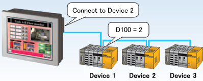
| When multiple devices are connected to operator interface, it's possible to change devices that the operator interface connects to if the [Indirect Device] feature is used. |
| |
|
| |
|
| |
|
| |
|
| For the [Indirect Device] feature, addresses to be specified for changing connected devices are internal devices (LS/USR area) in the operator interface only. To change devices on PLC, it's necessary to combine the [Indirect Device] feature with the [D-Script (or Global D-Script)]/[Logic] feature. |
| |
|
| |
|
| ■ Settings |
| 1. |
Make settings of the [Indirect Device] feature. (→How to set indirect devices) |
| 2. |
Using the D-Script (or Global D-Script) or Logic feature, write the value to [Device ID Address] of the [Indirect Device] from PLC. |
| |
|
| |
- When using the D-Script (or Grobal D-Script) feature |
| |
- When using the Logic feature |
| |
|
| |
| NOTE |
| D-Script is set to a base screen. While the base screen is displayed, a program is executed according to a trigger condition. For Global D-Script, while operator interface is running, a program is executed according to a trigger condition regardless of display screens. |
|
|
| |
|
| <When using the D-Script/Global D-Script feature> |
| 1. |
When using D-Script: |
| |
Click [D-Script] on the [Parts] menu. |
| |
When using Global D-Script: |
| |
Click [Global D-Script] on the [Common Settings] menu. |
| |
|
| 2. |
Click [Create]. |
| 3. |
Write a script to assign the value of a device address in PLC to [Device ID Address] specified in [Indirect Device]. |
| |
EX) |
[Device ID Address] of [Indirect Device] = "LS100"
The device address in PLC (PLC1) for device-switching control = "D100" |
| |
 |
| |
|
| |
| NOTE |
| Specify any [Trigger] for the D-Script above. |
| EX) |
|
 |
Specify [On Bit Change] for 0 bit of the internal device, LS2032, which toggles ON/OFF every communication cycle:
Every communication cycle, the D-Script program is excuted. |
| |
|
 |
Specify [On Bit Change] for 0 bit of the internal device, LS2038, which is the counter that increments each time the processing of the part displayed on the screen is completed:
Every time the screen processing is completed, the D-Script program is excuted. |
|
|
| |
|
| 4. |
Transfer the project file to the operator interface. |
| |
|
| |
|
|
| <When using the Logic feature> |
| 1. |
On [Screen List Window], double click [MAIN] of Logic Screens and open the logic edit screen. |
| |
 |
| |
|
| 2. |
Create logic program to assign the value of a device address in PLC to [Device ID address] specified in [Indirect Device]. |
| |
EX) |
[Device ID Address] of [Indirect Device] = "LS100"
The device address in PLC (PLC1) for device-switching control = "D100" |
| |
|
| 3. |
Store the value of D100 in LS100 using the transfer instruction, MOV. |
| |
 |
| 4. |
Transfer the project file to the operator interface. |
| |
|
| |
|


 沪ICP备05028659号-3