Is an error code displayed?
Cause
FLEX NETWORK unit settings may be incorrect.
Solution
Check the error code. See the following sections for the description and handling method of the error code.
![]() T.8 Errors displayed with an expansion unit
T.8 Errors displayed with an expansion unit
See the following sections for the description and handling method of the error code.
Can the device connected to the FLEX NETWORK board perform input and output functions normally?
Check whether the device connected to the FLEX NETWORK board performs input/output operations properly in order to determine whether the problem is in the GP or not.
![]()
For details about the setting screen, refer to the setting guide.
![]() M.18.3 Peripheral Settings Guide
M.18.3 Peripheral Settings Guide
When DIO (Example: FN-X16TS) is used
Go to offline mode and touch [Peripheral Settings] on the item changeover switch.
[Peripheral Settings] screen opens. Touch [I/O Driver] and then [FLEX NETWORK Driver].
[I/O Driver] screen opens. Touch [I/O Monitor].
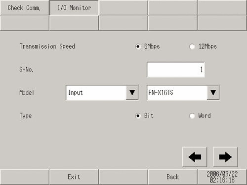
[I/O Monitor] screen opens. Set the [Transmission Speed], [S-No.], [Model], and [Type]. (Example, S-No.= 1, Model= Input FN-X16TS, Transmission Speed= 6Mbps, Type=Bit)
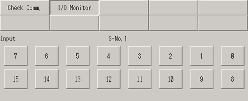
The bit monitor screen is displayed, showing the ON/OFF status. A protruding switch indicates OFF and a depressed switch indicates ON.
When the connection device is operating normally
When the connection device is operating normally, check the following GP-Pro EX settings because there is no problem with the Display side and the unit side:
Verify whether or not the correct unit is selected in [Unit (U)] in [I/O Driver Setting] in the [System Settings].
![]() 31.4.1 Procedure - Using FLEXNETWORK External I/O
31.4.1 Procedure - Using FLEXNETWORK External I/O
Check if [Run at Start Up] is set to [Run] in offline mode or in GP-Pro EX.
![]() 5.4.5 System Settings [Display Unit] - [Logic] Settings Guide
5.4.5 System Settings [Display Unit] - [Logic] Settings Guide
![]() M.19.1 [Home] Setting Guide
M.19.1 [Home] Setting Guide
Verify whether or not [Logic Programs] in [System Settings] is set to [Enable] in offline mode or with GP-Pro EX.
![]() 30.15.1 Logic Program Settings Guide
30.15.1 Logic Program Settings Guide
When the connection device is not operating normally
When the connection device is not operating normally, check the wiring of the Display and connected device and then the following items:
Check if the cable is functioning normally by performing a communication check.
Check whether the FLEX NETWORK unit connected to the FLEX NETWORK board can communicate properly.
![]()
For details about the setting screen, refer to the setting guide.
![]() M.19.3.1 Peripheral Settings - Check Communication
M.19.3.1 Peripheral Settings - Check Communication
Go to offline mode and touch [Peripheral Settings] on the item changeover switch.
[Peripheral Settings] screen opens. Touch [I/O Driver] and then [FLEX NETWORK Driver].
[I/O Driver] screen opens. Touch [Check Comm].
[Start]. Touch the button.
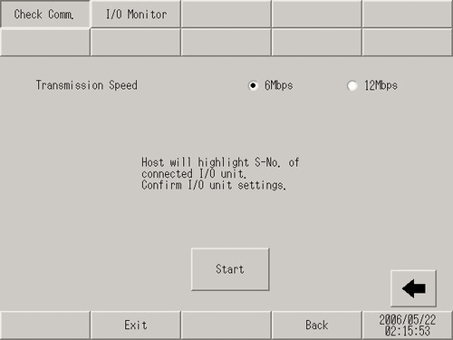
The communication check screen will display. When no problem is found with the communication, the total number of units that communicated successfully and the S-No assigned to the units are highlighted. If communication is successful, please check whether the device connected to the FLEX NETWORK unit operates properly or the cable is correct.
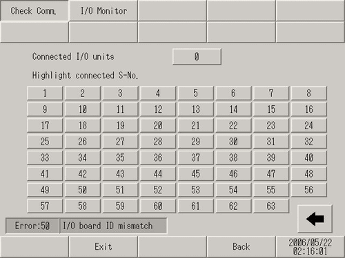
If communication fails, check the communication cable for breaks, the power supply of the unit, and the termination resistor of the unit. If the problem continues, the I/O unit or display unit may be faulty. Please contact the Pro-face customer care center.
![]() T.11.2 Telephone Contact
T.11.2 Telephone Contact
* The following list shows the I/O units supported by the communication check.
(Example) When setting FN-X16TS(1),1 S-No.1 and FN-XY32SKS (4),1,S-No.2, S-no.1 to 5 are highlighted on the screen above.
|
Type |
Model |
Number of stations |
|---|---|---|
|
DIO |
FN-X16TS |
1 |
|
FN-X32TS |
2 |
|
|
FN-Y08RL |
1 |
|
|
FN-Y16SK |
1 |
|
|
FN-Y16SC |
1 |
|
|
FN-XY08TS |
1 |
|
|
FN-XY16SK |
1 |
|
|
FN-XY16SC |
1 |
|
|
FN-XY32SKS |
4 |
|
|
Analog |
FN-AD02AH |
1 |
|
FN-AD04AH |
4 |
|
|
FN-DA02AH |
1 |
|
|
FN-DA04AH |
4 |
|
|
High Speed Counter Unit |
FN-HC10SK |
8 |
|
Single-Axis Positioning Unit |
FN-PC10SK |
4 |