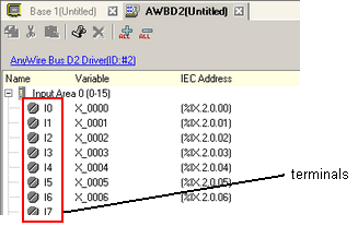
The input area or output area set up in the [I/O Driver Settings] are shown on the I/O Screen as I/O terminals for each AnyWire slave unit. You can control the I/O by mapping variables to the I/O terminals.
For example, when you are using the AnyWire slave unit's input terminal and you want to map the 100th bit in the transmission frame, map a variable to "I4" of input area 6 (96-111).
![]()
You can use 448 input points and 448 output points with one AnyWire master unit.
For AnyWire slave unit settings, see the manual for your unit.
I/O Screen Display
The I/O Screen's terminal display will differ depending on the input type and output type you set up in [I/O Driver Settings].
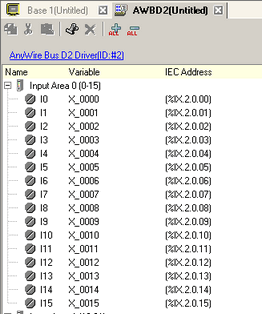
Example 1: When the type is "Bit"
Bits are displayed in one terminal.
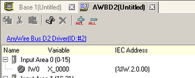
Example 2: When the type is "Integer"
Integers are displayed in one terminal.
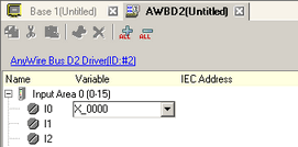
Mapping Variables
Mapping variables to a terminal. to define a variable, double-click the [Variable] column of the terminal you want to map. The [IEC Address] is populated after entering a variable.
|
Data Type |
Input |
Output |
|
Bit |
IX |
QX |
|
Integer |
IW |
QW |
![]()
You can use the following values for variables.
Bit: ON or OFF
Integer: 0 to 65535