In [IO Driver Settings] click [Settings] and add HTB to the network.
![]() 31.7.1 Setting Up CANopen
31.7.1 Setting Up CANopen
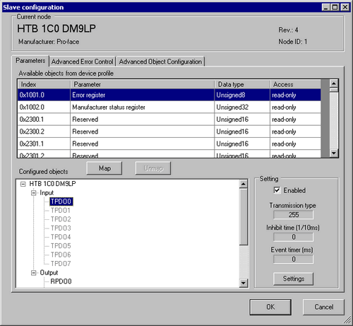
Set standard input and output of HTB.
![]() 31.7.5.3 Procedure - HTB Standard Input/Output
31.7.5.3 Procedure - HTB Standard Input/Output
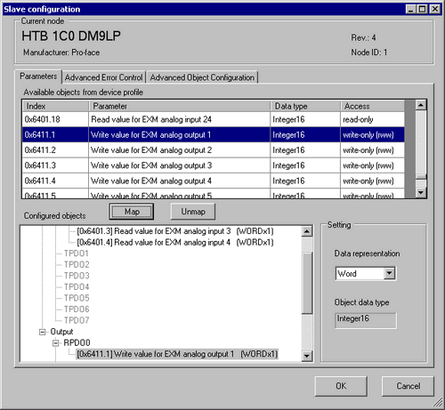
Set up analog input of EX module. Select the input value object "0x6401.1 to 0x6401.4" to map to TPDO. In [Settings], select the data type. In addition, map "0x6411.1" to RPDO and select the data type.
![]()
-
Map the input data from HTB (CANopen slave) to the display unit (CANopen master) for TPDO, and map the object relating to the output data from the display unit to HTB for RPDO.
-
Map error register "0x1001.1", status register "0x1002.1", and module diagnosis "0x3000.1", "0x3000.2" and "0x3000.2" to TPDO as required.
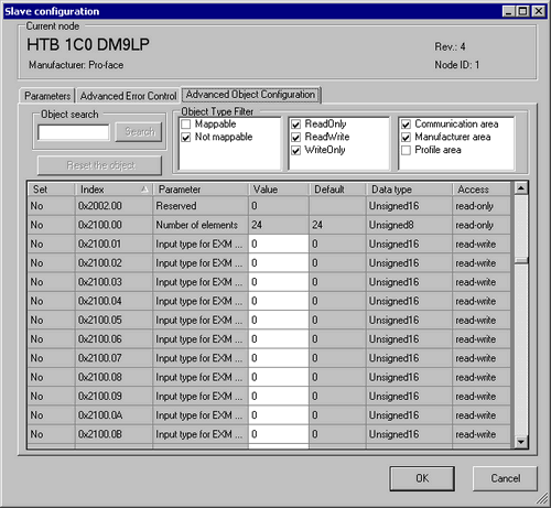
Open [Advanced Object Configuration] tab and configure detailed settings of the object. Set the data type of analog input (0x2100.1 to 0x2100.4) and the data type of analog output (0x2200.1).
Set the data range (Input: 0x2101.1 to 0x2101.4, output: 0x2201.1), PDO transmission enabled/disabled (0x6423), fallback mode (0x6443.1) and fallback value (0x6444.1), and then click [OK] to close the dialog box.
![]()
-
For details of objects, refer to the following.
 31.7.10 Communication Setting HTB Objects (1000h to 1FFFh)
31.7.11 Manufacturer HTB Object (2000h to 5FFFh)
31.7.12 Standard Device HTB Object (6000h to 9FFFh)
To assign variables to each mapped object, in [I/O Driver] click [I/O Screen], or from the Workspace menu select [Screen List] and then click the I/O screen. For information on how to assign variables, refer to the following.
![]() 31.7.3 Mapping I/O - CANopen
31.7.3 Mapping I/O - CANopen
Create a Logic Screen and a Base Screen to access the allocated variables and transfer them to the display unit.
![]()
-
To check set values, use SDOR instructions.
-
When changing the analog setting value with SDOW instructions, you need to use the expansion bus reset (0x3300) to stop the internal bus before making the change.