LT3000 Series
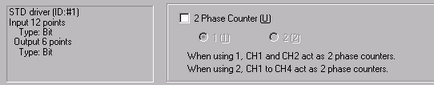
Depending on whether or not the high-speed counter (2-phase counter) is used, the combination differs as follows.
2-phase counter not used (CH1 to CH4)
There are ten setting patterns.
Setting Patterns |
Input Terminal (n) |
Input Terminal (n+1) |
Output Terminal |
Standard |
Standard Input |
Standard Input |
Standard Output |
PWM |
PWM Output |
||
PLS |
PLS Output |
||
High Speed Counter Unit Standard |
Counter Input |
Standard Input |
Standard Output |
High Speed Counter Standard |
Synchronize output |
||
High Speed Counter Preload |
Preload Input |
Standard Output |
|
High Speed Counter Preload |
Synchronize Output |
||
High Speed Counter Prestrobe |
Prestrobe Input |
Standard Output |
|
High Speed Counter Prestrobe |
Synchronize Output |
||
Pulse Catch |
Pulse Catch Input |
Standard Input |
Standard Output |
One 2-phase counter (CH1)
There are six setting patterns.
Setting Patterns |
Input Terminal (n) |
Input Terminal (n+1) |
Output Terminal |
Counter A (Phase A) Standard Input |
Counter A (Phase A) |
Standard Input |
Standard Output |
Counter A (Phase A) Standard Input |
Synchronize Output |
||
Counter A (Phase A) Preload |
Preload Input |
Standard Output |
|
Counter A (Phase A) Preload |
Synchronize Output |
||
Counter A (Phase A) Prestrobe |
Prestrobe Input |
Standard Output |
|
Counter A (Phase A) Prestrobe |
Synchronize Output |
One 2-phase counter (CH2)
There are six setting patterns.
Setting Patterns |
Input Terminal (n) |
Input Terminal (n+1) |
Output Terminal |
Counter B (Phase B) Marker |
Counter B (Phase B) |
Marker Input |
Standard Output |
Counter B (Phase B) Marker |
PWM Output |
||
Counter B (Phase B) Marker |
PLS Output |
||
Counter B (Phase B) Standard Input |
Standard Input |
Standard Output |
|
Counter B (Phase B) Standard Input |
PWM Output |
||
Counter B (Phase B) Standard Input |
PLS Output |
![]()
CH3 and CH4 when one 2-Phase Counter is used are the same as CH1 to CH4 when 2-Phase Count is not used.
Two 2-phase counters (CH1 and CH3)
There are six setting patterns.
Setting Patterns |
Input Terminal (n) |
Input Terminal (n+1) |
Output Terminal |
Counter A (Phase A) Standard Input |
Counter A (Phase A) |
Standard Input |
Standard Output |
Counter A (Phase A) Standard Input |
Synchronize Output |
||
Counter A (Phase A) Preload |
Preload Input |
Standard Output |
|
Counter A (Phase A) Preload |
Synchronize Output |
||
Counter A (Phase A) Prestrobe |
Prestrobe Input |
Standard Output |
|
Counter A (Phase A) Prestrobe |
Synchronize Output |
Two 2-phase counters (CH2 and CH4)
There are six setting patterns.
Setting Patterns |
Input Terminal (n) |
Input Terminal (n+1) |
Output Terminal |
Counter B (Phase B) Marker |
Counter B (Phase B) |
Marker Input |
Standard Output |
Counter B (Phase B) Marker |
PWM Output |
||
Counter B (Phase B) Marker |
PLS Output |
||
Counter B (Phase B) Standard Input |
Standard Input |
Standard Output |
|
Counter B (Phase B) Standard Input |
PWM Output |
||
Counter B (Phase B) Standard Input |
PLS Output |
LT4000 Series
Input and output terminals are determined based on which channels you are using, and which functions you are setting on the channel.
![]()
There are 4 channels in the LT4000 Series. CH1 and CH3, and CH2 and CH4 are in the same groups in the setting screen.
You cannot use the same input/output terminals within a group.
Standard Input/Output and Special I/O
Feature |
Channel |
Input pin |
Output Terminal |
Standard (DIO model) |
CH1 - CH4 |
X0 - X19 |
Y3 - Y11 |
Standard (analog model) |
CH1 - CH4 |
X0 - X11 |
Y3 - Y7 |
PWM Output |
CH1, CH3 |
X4, X5 |
Y0 |
CH2, CH4 |
X6, X7 |
Y1 |
|
Pulse output |
CH1, CH3 |
X4 |
Y0 |
CH2, CH4 |
X4 |
Y1 |
|
Pulse Output (2 Phase) |
CH3 & 4 |
X4 |
Y0, Y1 |
High Speed Counter |
CH1, CH3 |
X0, X2 |
Y0 |
CH2, CH4 |
X1, X3 |
Y1 |
|
High Speed Counter (2-Phase) |
CH1 & 2 |
X0, X1, X2, X3 |
Y0, Y1 |
Pulse Catch |
CH1, CH3 |
X0 |
- |
CH2, CH4 |
X1, X3 |
- |
Voltage/Current Input/Output and Temperature Input
Feature |
Channel |
Input pin |
Output Terminal |
Voltage/Current Input |
- |
IV0, IV1 |
- |
Voltage/Current Output |
- |
- |
U/I0, U/I1 |
Temperature Input |
Channel 1 |
EX0+, EX0-, MS0+, MS0- |
- |
Channel 2 |
EX1+, EX1-, MS1+, MS1- |
- |